Capacitance meter based on logic gates
Radio 1989, 4
This simple capacitance meter circuit can be assembled even by a novice. The accuracy of measurement of this device is about 4%, that is that is satisfactory for amateur purpose.
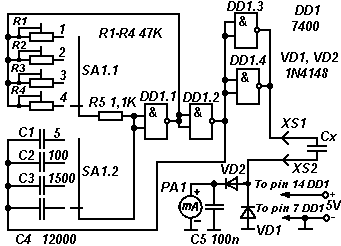
The circuit is shown in figure 1. The device has four subranges, determined by position of the switch SA1. In the position "1" it measures capacitance in the range up to 50pF, 2 - 500pF, 3 - 5000pF, and 4 - 0.05uF.

Fig. 1. Circuit diagram of the capacitance meter.
DD1 - 7400; VD1, VD2 - 1N4148;
R1-R4 - 47K; R5 - 1.1K;
C1 - 5pF; C2 - 100pF; C3 - 1500pF; C4 - 12000pF; C5 - 0.1μF;
SA1 - 4 way switch; PA1 - full-scale
deflection milliammeter of 1mA.
The NAND logic gates DA1.1 and DA1.2 forms square wave oscillator. The circuit will oscillate at the frequency determined by the capacitor and the resistor in the feedback network. The frequency has the maximum value at the position "1" of the switch SA1, and it has minimum value at the position "4".
The logic gates DD1.3 and DD1.4 is connected in parallel. This way of connection provides higher charging current for the capacitor with unknown value Cx, that is connected to the terminals XS1 and XS2. Increasing the charging current allows to minimize effect of leakage resistance of the capacitor with unknown value Cx.
The indication provides by the DC analog moving coil type of meter with range of 1 mA and with resistance of 240 ohms. The diodes VD1 and VD2 must be high speed types.
The calibration of the capacitance meter doing separately for the each range. The switch SA1 switches in the corresponding position. Connect a capacitor with the known value to the terminals XS1 and XS2. Adjust the potentiometer R1 so that the meter gives full scale deflection. Repeat it for the subranges 2,3 and 4.
Mlad konstruktor, 1987, 9